Von den 36 Standard-Anlotungen sind 12 im Minimalprogramm (rot gekennzeichnet)
01: PLAX-Scout (Parasternale lange Achse Übersicht)
- Pleuraerguss, Perikarderguss
- Ventrikel senkrecht zum Ultraschall
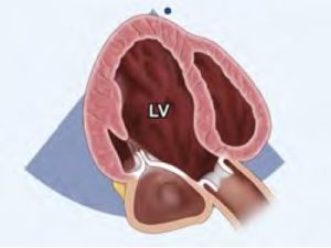
02: PLAX-LV
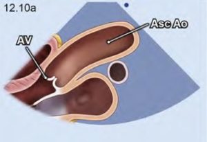
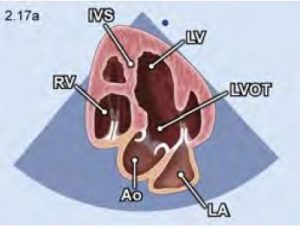
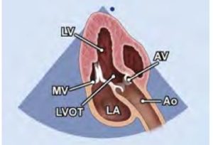
03: PLAX-AV
- möglicherweise andere Position, höher
- Messung von Sinus, Sinotub. Übergang, Ascendens
- endexpiratorisch hilfreich
04: R-PLAX
- auch für Dopplermessungen (Stiftsonde)
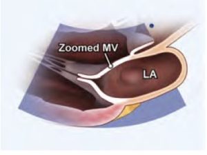
05: PLAX-MV
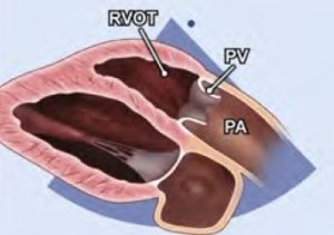
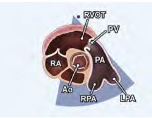
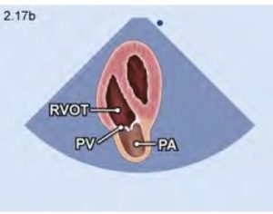
06: PLAX-RVOT
- anterior kippen und leicht im Uhrzeigersinn drehen
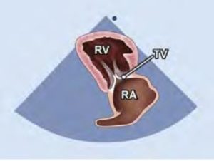
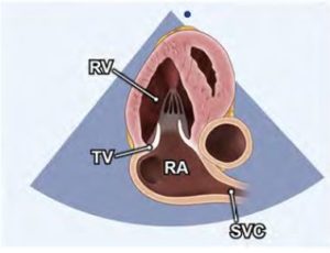
07: PLAX-RVIT
– inferior kippen und etwas gegen den Uhrzeigersinn drehen
– TV: anteriores Segel
– TV: septales Segel wenn Setum sichtbar, sonst posteriores Segel
– anteriore und inferiore Wand des RV
– Eustachsche Klappe
– Coronarsinus
– VCI
08: PSAX-AO
– PA
– Aorta über der Klappe
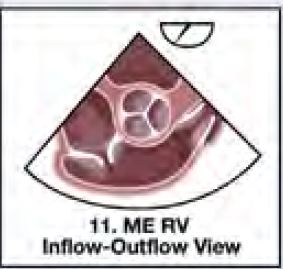
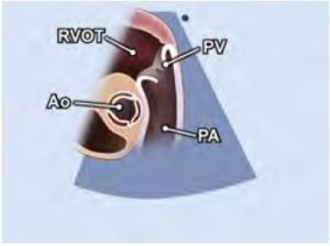
09: PSAX-RVOT
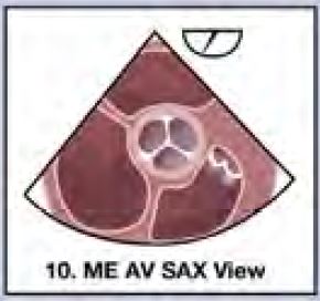
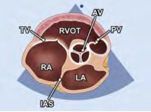
10: PSAX-AV
– mit LA, Septum etc
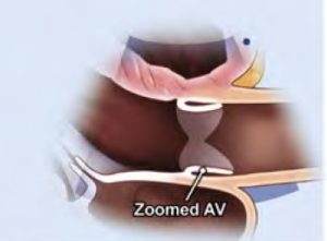
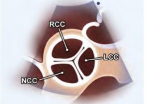
11: PSAX-AV-Zoom
– Taschen
– HS
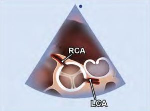
12: PSAX-CA
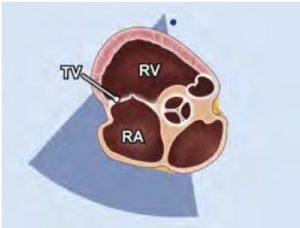
13:PSAX-TV
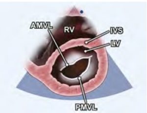
14:PSAX-MV (Parasternale kurze Achse in Höhe der Mitralklappe)
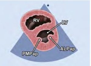
15: PSAX-PM (Parasternale kurze Achse in Höhe der Papillarmuskeln)
16: PSAX-Apex (Parasternale kurze Achse in Höhe der Herzspitze)
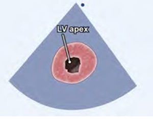
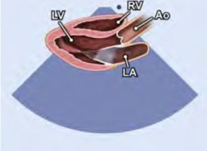
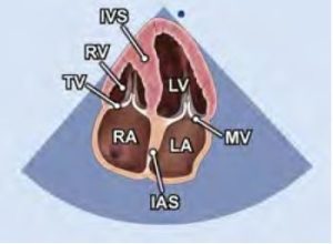
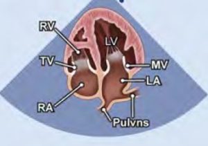
17: A4C (4-Kammerblick Übersicht)
- 2/3 LV, 1/3 LA
- Apex elliptisch (nicht rundlich)
- RV triangulär
- Moderatorband im RV
- septales TK-Segel innen, anteriores oder posteriores außen
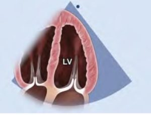
18: A4C-LV (LV-focusierter 4-Kammerblick)
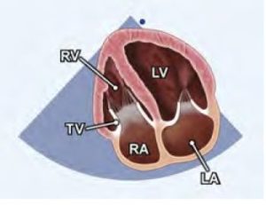
19: A4C-RV (RV-fokusierter 4-Kammerblick)
- leicht gegen den Uhrzeigersinn gedreht
- für TAPSE sollte der Annulus gezoomt werden
- für RV-strain
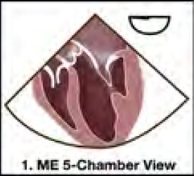
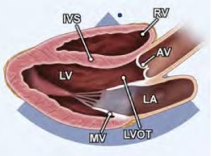
20: A5C (5-Kammerblick)
21: A-RVOT
- vom A5C-Blick noch weiter nach anterior gekippt
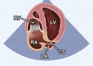
22: A4C-CS
- vom A4K nach posterior gekippt
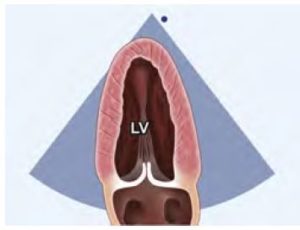
23: A2C-LV
- vom A4C um 60 Grad gegen den Uhrzeigersinn gedreht
24: A2C-RV
- vom RV fokusierten A4C 60 Grad gegen den Uhrzeigersinn
- Katheter und SM-Sonden von der VCS evaluieren,
- Evaluation der TI
- Inferiore Wand des RV (Rechtsherzinfarkt).
25: A3C
- weitere 60 Grad gegen den Uhrzeigersinn gedreht
26: A3C-LV
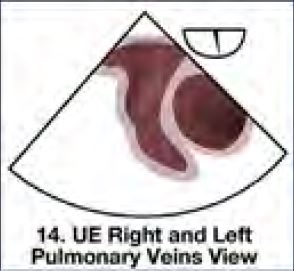
27: A4C-PVN
- Anlotung mit der maximalen LA-Größe
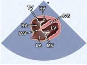
28: SC-4C
- Inspiration hilft
- Septumdefekte
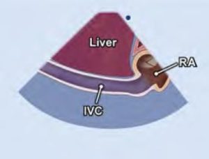
29: SC-VCI
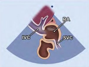
30: SC-VCS
-vom VCI-Blick Schallkopf nach oben ziehen
31: SC-SAX
- 90 Grad gegen den Uhrzeigersinn

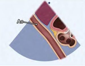
32: SC-AAb
- vom VCI-Blick nach links schwenken
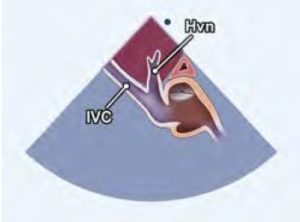
33: SC-HVN
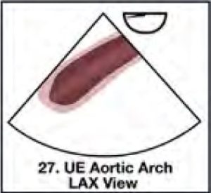
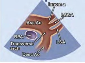
34: SSC-LAX
- Index gegen 12 Uhr
- Rechte Pulmonalarterie im Querschnit
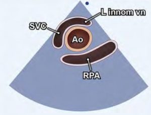
35: SSC-SAX
- um 90 Grad drehen und nach unten kippen
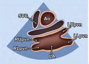
36: SSC-SAX-PVN (Suprasternaler Kurzachsenblick auf Pulmonalvenen, Crab view)
- noch mehr kippen, fast parallel zm Sternum
Mitchell C, Rahko P, Blauwet L, Canaday B, Finstuen J, Foster M, Horton K, Ogunyankin K, Palma R and Velazquez E (2018) Guidelines for Performing a Comprehensive Transthoracic Echocardiographic Examination in Adults: Recommendations from the American Society of Echocardiography. Journal of the American Society of Echocardiography : official publication of the American Society of Echocardiography.